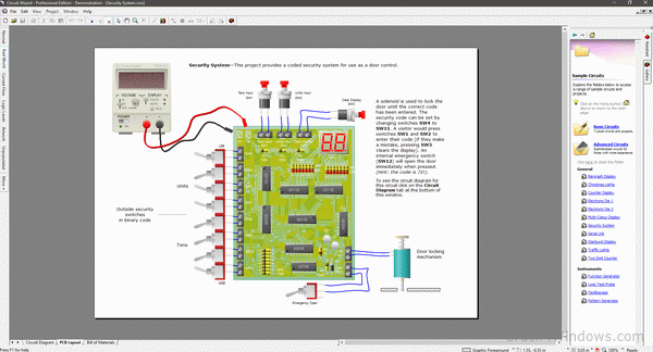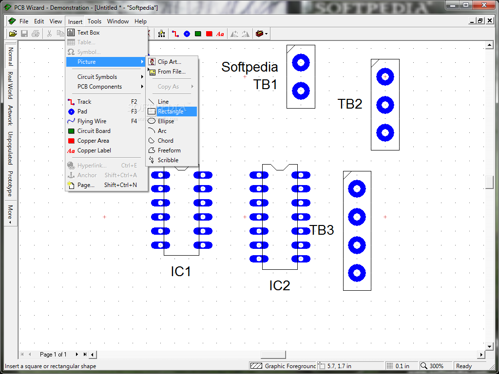
CIRCUIT WIZARD is one of the best software which allows real time simulation of circuit from basic level to higher level circuit It also allows us to animate. MICROWIND version 3.5 with many new and exciting features. Of 32nm & 45nm technology design rule file with their application notes. The MICROWIND software allows the designer to simulate and design an integrated circuit at physical description level. File: Circuit Wizard 3.5 Education Demo (60.1 MB) To download Circuit Wizard 3.5 Education demonstration software, please complete the form below.
You will need at least the following specification to run Circuit Wizard: IBM-compatible PC with an x86 processor (CPU) Microsoft Windows XP, Vista, 7 or 8 Operating System (OS) 256 MB of (RAM) memory (memory requirement excludes that required by your OS) 100 MB of available hard-disk space VGA or higher-resolution monitor Microsoft mouse or compatible pointing device.
Circuit Wizard Downloads
From this page you can download a range of sample circuits as well as working versions of the circuits used throughout the series.
Important Note Regarding Circuit Wizard Sample Files: The Circuit Wizard software is available in three different versions; Standard, Professional and Education. The availability of certain sample files, components and/or equipment will depend on the version of the software that you have purchased. The circuits provided below are compatible with the Education version. This is the version used by schools/college (our primary audience for the teach-in series). Readers with alternative versions of the software should follow the tutorials within the series to create their own files as is the intention of the series. Regrettably we are unable to provide our sample files in every possible format. |
Circuits By Teach-In Part

Circuit Wizard 3.5 Download

| Part 2 : Ohm's Law Sample Circuit Our replacement Ohm's Law sample circuit for readers who do not have this included in their version of Circuit Wizard. |
| Part 3 : Testing Diodes Inclides 1N4001 in forward and reverse bias as well a Zener diode testing circuits |
| Part 3 : Transistor Oscillator A simple two LED 'flasher' circuit utilising two NPN transistors |
| Part 4 : Transistor Theory Circuit A circuit showing the voltages/currents in a simple common collector transistor switching citcuit |
| Part 4 : 555 Motor Pulse Circuit A circuit using a 555 timer IC with a transistorised output to pulse a DC motor |
| Part 4 : Transistor Amplifier A transistor based signal amplifier |
| Part 5 : Inverting Operational Amplifier An operational amplifier in an inverting configuration with a variable voltage input |
| Part 5 : Inverting Operational Amplifier With Signal Input As above but with a signal input. |
| Part 5 : Comparator Using an operational amplifier as a comparator |
| Part 5 : Dark Sensing Automatic Light This circuit uses an operational amplifier comparator to sense light level and control a mains lamp |
| Part 5 : Square Wave Generator This circuit uses an operational amplifier to generate a square wave |
| Part 6 : Logic Gate Worksheet An interactive worksheet to print out and experiment with the basic logic gates |
| Part 6 : Combinational Logic Example Simulate the circuit... could this be replaced by just one single gate? |
| Part 6 : NAND Equivalents Simulator Demonstrating various NAND gate equivalents for common logic gates |
| Part 6 : Intruder Alarm Circuit An intruder alarm circuit using an OR gate |
| Part 6 : 4-bit Ripple Counter This logic circuit produces a binary count |
| Part 6 : 0-9 Counter This circuit uses the ripple counter (above) and a 7-Segment LED driver/display to show a 0-9 count |
| Part 7 : 555 Kitchen Timer A kitchen timer using a 555 in a monostable configuration |
| Part 7 : 555 Bistable A simple 555 'on-off' circuit |
| Part 7 : 555 Astable A 555 alternate LED flasher circuit |
| Part 7 : Red/Green Signal Circuit Uses a 555 to set either red or green |
| Part 7 : 555 Clocked Counter Uses a 555 to clock a 4-bit ripple counter driving a 7-segment display |
| Part 7 : 556 Flasher Sequence Circuit 556 dual timer used to sequence flashes |
| Part 8 : 1st Order Low Pass Filter A basic 1st order low pass filter circuit |
| Part 8 : 1st Order High Pass Filter A basic 1st order high pass filter circuit |
| Part 8 : 2nd Order Low Pass Filter A basic 2nd order low pass filter circuit |
| Part 8 : 2nd Order High Pass Filter A basic 2nd order high pass filter circuit |
| Part 9 : 4-bit DAC A simple 4-bit binary-weighted DAC |
| Part 9 : 4-bit DAC with unity inverter The simple 4-bit binary-weighted DAC with a unity inverter |
| Part 9 : Improved 4-bit DAC 4-bit binary-weighted DAC with differential output |
| Part 9 : 4-bit DAC using analogue switches An imporved 4-bit binary-weighted DAC using analogue switches |
| Part 9 : 4-bit DAC using R-2R ladder An improved 4-bit binary-weighted DAC using an R-2R ladder network |
| Part 10 : Light Sensor (no PCB) Light sensor circuit (no PCB layout) |
| Part 10 : Light Sensor with PCB Light sensor circuit with example generated PCB layout |
| Part 10 : 555 Flasher (no PCB) 555 flasher circuit (no PCB layout) |
| Part 10 : 555 Flasher with PCB 555 flasher circuit with example generated PCB layout |

Further Sample Circuits
Circuit Wizard Download Full Version

Circuit Wizard Software
| Sample Circuits ...further sample circuits coming soon! |